ABOUT HIKI TEC., JSC
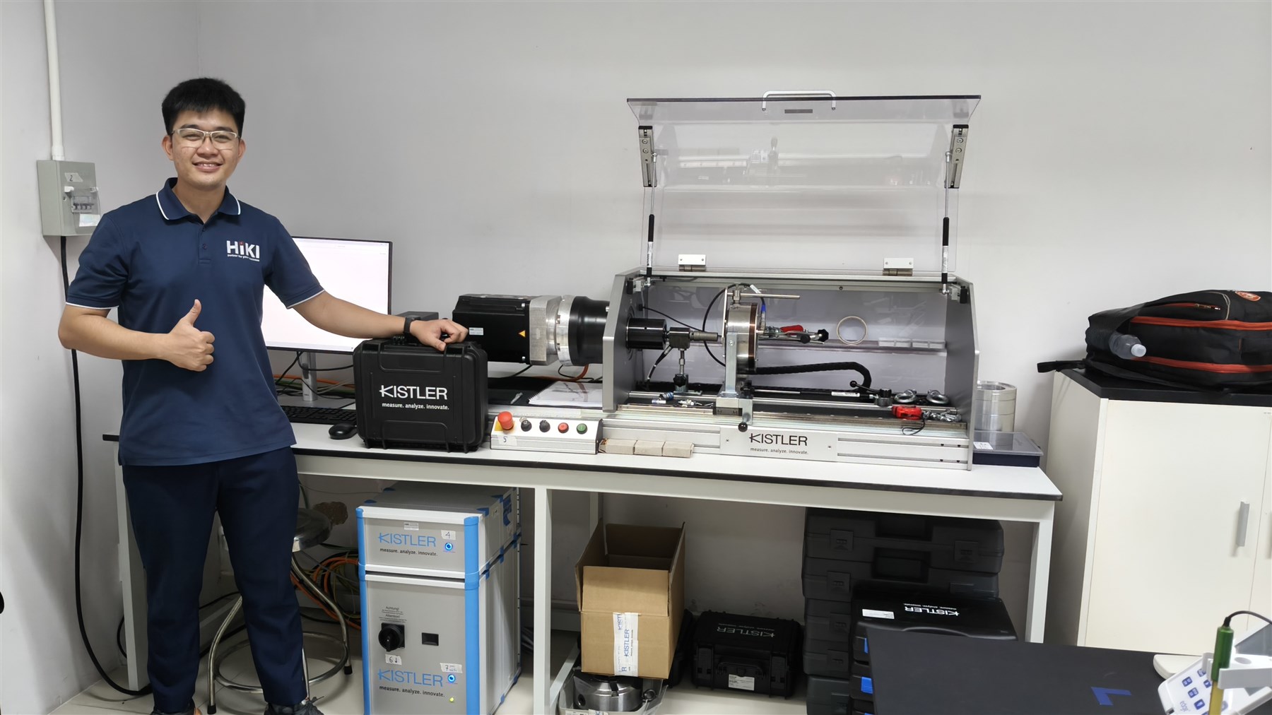
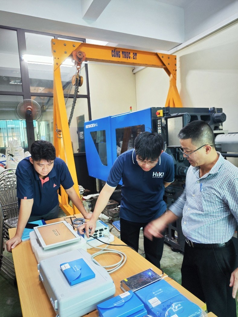
HIKI TEC., JSC provides Test & Measurement and Industrial Automation solutions. Our scope of works include consultation, trading, commissioning and after sales support.
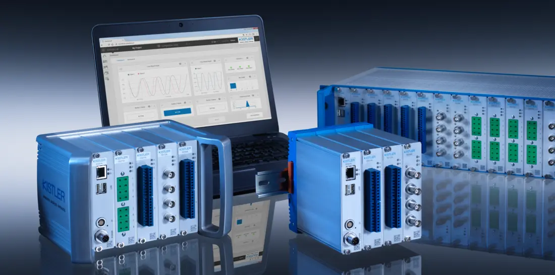
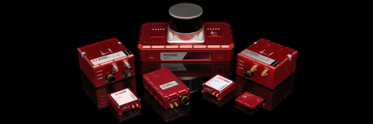
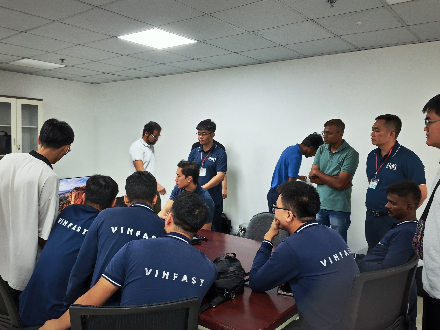
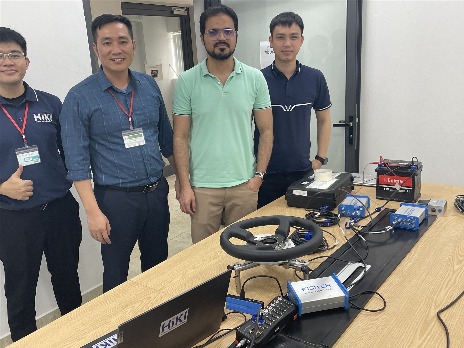
We proudly deliver world-class products from leading global brands. Our products are being used in R&D and Manufacturing activities across Laboratories, Research Institutes, Testing Centers, Universities, and Industrial Production Facilities.
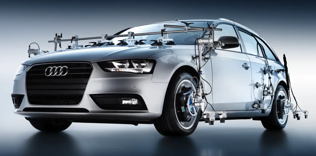
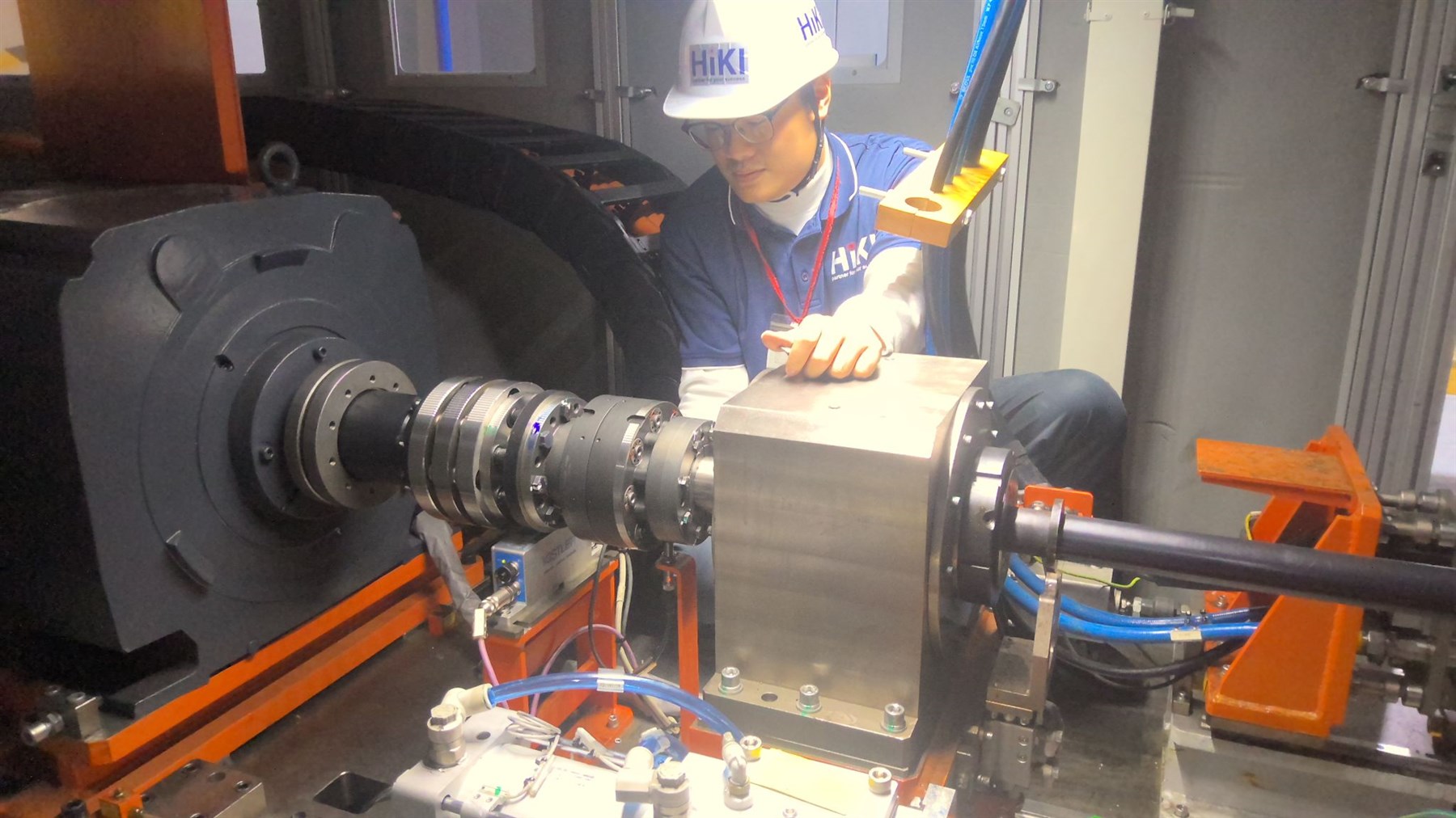
With deep expertise in our field and over 15 years of hands-on experience in Test & Measurement and Industrial Automation, we supply solutions which are highly valued by clients across diverse sectors—including Automotive R&D and Manufacturing, Aerospace & Defense, Education & Training, Mechanical & Materials Engineering, Electrical & Electronics, and Transport & Civil Engineering.
Download HIKI Catalogue Solutions & Products